


MTW European Type Trapezium Mill
Input size:30-50mm
Capacity: 3-50t/h
LM Vertical Roller Mill
Input size:38-65mm
Capacity: 13-70t/h

Raymond Mill
Input size:20-30mm
Capacity: 0.8-9.5t/h

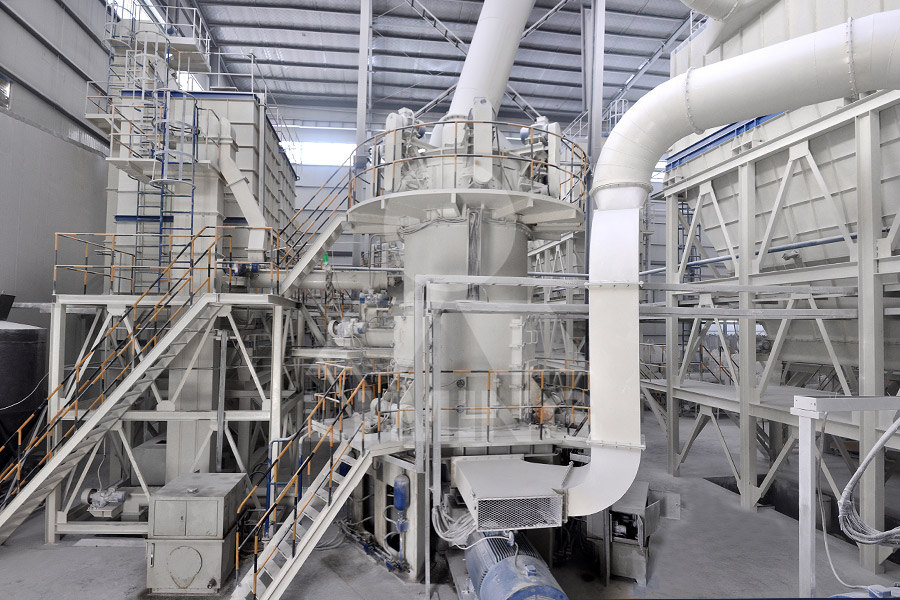
Sand powder vertical mill
Input size:30-55mm
Capacity: 30-900t/h

LUM series superfine vertical roller grinding mill
Input size:10-20mm
Capacity: 5-18t/h

MW Micro Powder Mill
Input size:≤20mm
Capacity: 0.5-12t/h

LM Vertical Slag Mill
Input size:38-65mm
Capacity: 7-100t/h
LM Vertical Coal Mill
Input size:≤50mm
Capacity: 5-100t/h
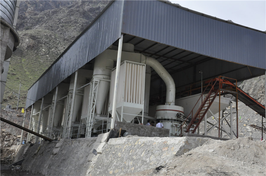
TGM Trapezium Mill
Input size:25-40mm
Capacity: 3-36t/h

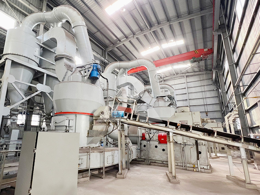
MB5X Pendulum Roller Grinding Mill
Input size:25-55mm
Capacity: 4-100t/h
Straight-Through Centrifugal Mill
Input size:30-40mm
Capacity: 15-45t/h
Grinding machine structure schematic diagram
.jpg)
14 Types of Grinding Machines (Working, Diagram PDF)
The document discusses 14 types of grinding machines including bench, hand, pedestal, portable, flexible, and precision grinders Precision grinders include cylindrical, plunge cut, form, Figure 2 shows the schematic diagram of the grinding machine and instrumentation used The tests were carried out for 15 different grinding conditions, using 5µm as the lowest depth ofSchematic diagram of the grinding machine and This paper deals with the optimal structural design of a Biglide parallel grinder for drill grinding A pair of spatial modules is adopted to replace the conventional parallelogram to enhanceSchematic diagram of the grinder Download Scientific Download scientific diagram Schematic illustration of a grinding machine from publication: A novel hybrid whale–Nelder–Mead algorithm for optimization of design and manufacturing Schematic illustration of a grinding machine Download Scientific
Different Types of Grinding Machine IJRPR
Grinding machines use highspeed spinning abrasive wheels to create flat, cylindrical, and other surfaces Grinding is a machining operation that is used to improve the accuracy of a product 2023年8月23日 A surface grinding machine is a precision machining tool that utilises a grinding wheel as a cutting tool to remove material from the surface of the workpiece This abrasive machining process involves placing abrasives on Surface Grinding Machine: Diagram, Parts, Working, 2023年10月6日 A cylindrical grinding machine is a precision tool used in machining operations to grind cylindrical surfaces and create smooth, cylindrical workpieces It employs abrasive wheels to remove material, achieving high Cylindrical Grinding MachineDiagram, Parts, Working, shown in Fig 5 The related machines are according to their appearance, structure, and functionality different in every respect, which shows the limitation of a classification scheme Grinding Machines
.jpg)
The Ultimate Guide to Understanding CNC Machine Schematic Diagrams
Section 7: Best Practices for CNC Machine Schematic Diagrams Techniques for organizing and labeling schematic diagrams Importance of documentation and keeping schematic diagrams up to date Section 8: Future Developments in CNC Machine Schematic Diagrams Overview of emerging technologies and advancements in schematic diagrams for CNC machines2023年10月6日 Cylindrical Grinding Machine: Know Diagram, Parts, Working, Types and Applications Last Updated on Oct 6, 2023 Download as PDF Overview Test Series A cylindrical grinding machine is a vital tool in precision Cylindrical Grinding MachineDiagram, Parts, The grinding disc is not confined to a cylindrical form and is able to come up with a multitude of possibilities That will be useful for moving various geometries in accordance with the objects Read More :Types of Grinding Machine Types Surface Grinding Machine: Types, Parts Working system for the grinding machine Fig 4 The hardware configuration of the CNC system for grinding machine Fig 5 Fabrication of micro Vgrooves array on grinding machine a Schematic diagram of axes motions b Basic parameters of Vgrooves array 2144 Int J Adv Manuf Technol (2018) 97:2141–2150Development of a precision grinding machine system for the
How to Interpret and Use a Milling Machine Schematic Diagram
A milling machine schematic diagram is a visual representation of the components and electrical connections within a milling machine It provides a clear and organized view of the machine’s internal structure, allowing users to understand how different parts interact and how electrical signals flow throughout the system18 Abrasive Machining Processes In Figures (51) and (52), CE is the distance moved by the table during the time the grinding wheel makes 1/ N′ revolutionHere, N′ is the number of active abrasive grains on the grinding wheel surface Let, Vt be the worktable speed and N be the grinding wheel speed (RPM)UNIT 5 MECHANICS OF GRINDING AND and Grinding Operation Download scientific diagram (a) Schematic diagram of rail grinding machine, (b) contact mode of grinding test 1Inverter motor; 2Rail specimen; 3Grinding wheel; 4Wheel fixture; 5Slider; 6 (a) Schematic diagram of rail grinding machine, (b) contact Download scientific diagram The grinding setup and schematic diagram of grinding machine with (a) grindpolishing wheel, and (b) #8000 diamond wheel from publication: High surface integrity The grinding setup and schematic diagram of grinding machine
.jpg)
Types Of Surface Grinding machine with Diagram Explained
Types Of Surface Grinding machine with Diagram Explained Surface grinding machine: This machine may be similar to a milling machine used mainly to grind flat surface However, some types of surface grinders are also capable of producing contour surface with Download scientific diagram The schematic diagram of a grinding shaft from publication: A thermal deformation prediction method for grinding machine’ spindle Thermal deformation is the main The schematic diagram of a grinding shaft ResearchGateOverall, the ball mill diagram provides a visual representation of the key components and working principle of a ball mill It helps in understanding the process of grinding and how the grinding media and material interact within The Ultimate Guide to Understanding Ball Mill Download scientific diagram Rail grinding friction machine: (a) schematic diagram; (b) the position of acceleration sensor; (c) grinding specimens from publication: Influence of granularity of Rail grinding friction machine: (a) schematic

Schematic diagram of rail grinding machine and the friction pair
Download scientific diagram Schematic diagram of rail grinding machine and the friction pair of rail grinding aSiemens inverter motor bFoundation bed cMachine rail dTiming belt drive e 2019年4月8日 Grinding wheel structure diagram is shown in Fig 4 The matrix material is related to the bonding agent; the metalbonded abrasive tools usually use iron or copper alloy; resinbonded abrasive tools use aluminum and aluminum Design of Tools, Grinding Wheels, and Precision Spindles2024年10月5日 Highspeed grinding (HSG) is an advanced technology for precision machining of difficulttocut materials in aerospace and other fields, which could solve surface burns, defects and improve surface integrity by increasing the linear speed of the grinding wheel The advantages of HSG have been preliminarily confirmed and the equipment has been built for Highspeed grinding: from mechanism to machine toolDownload scientific diagram Schematic diagram of the ultrasonic vibration system from publication: Structural Design of a Special Machine Tool for Internal Cylindrical UltrasonicAssisted Schematic diagram of the ultrasonic vibration system
Understanding the Inner Workings of a Lathe Machine: A Schematic Diagram
Schematic Diagram of Lathe Machine A lathe machine is a versatile machine tool used in metalworking operations It is used to shape various workpieces by rotating them against a cutting tool A schematic diagram of a lathe machine provides an overview of its key components and how they work together Bed: The bed is the foundation of the lathe Download scientific diagram Microgrinding machining scheme and photo of mold core: (a) Schematic diagram of Vgrooved structures machining; (b) Photo of microgrinding from publication Microgrinding machining scheme and photo of mold core: (a) Schematic 2024年1月15日 Sidebyside comparison of the wiring diagram (drawing), the actual device, and the circuit schematic of the output circuits (MOSFET and Zener diode visible) Image used courtesy of the author Many devices exist in both diagrams and schematics Both will contain indicators, relays, power supply connections, transformers, fuses, and othersElectrical Drawings, Schematics, and Wiring Diagrams: How to Download scientific diagram Schematic diagram of the grinding process from publication: Influences of milling and grinding on machined surface roughness and fatigue behavior of a GH4169 Schematic diagram of the grinding process ResearchGate
.jpg)
Schematic diagram of electrochemical grinding
Download scientific diagram Schematic diagram of electrochemical grinding from publication: Experimental Investigation on Electrochemical Grinding of Inconel 718 Electrochemical grinding (ECG 2024年10月11日 In this paper, a combination of LSWEDM and electroplating process is used for the preparation of SSGTRAS substrate, Fig 1a shows the machining schematic diagram of the rotary machine equipped on LSWEDM, points M and N are the corresponding points of the starting and ending positions of the helical groove structural part in the coordinate system xoy, Modeling of surface generation and process experiments for grinding Turbine blades are mostly machined by grinding [3], which enables manufacturers to meet high precision and surface roughness requirements [4] Another, and the most expensive way to machine heat Schematic diagram of the grinding systemDownload scientific diagram Schematic diagram of the structure and motion axis of the cycloidal gear grinding machine from publication: Construction and Simulation of Failure Distribution Model Schematic diagram of the structure and motion axis of the
.jpg)
Drilling Machine: Definition, Parts, Operation, Types,
2022年2月23日 The radial drill machine has a singlespindle machine intended for handling large and heavy work which is beyond the capacity of the simple machine It consists of a vertical column with a radial arm that can swing through an arc of 180 degrees or moreDownload scientific diagram Engine piston skirt structure schematic 1 from publication: Optimization of the grinding trajectory of the engine piston skirt robot based on machine vision In this Engine piston skirt structure schematic 1 Download Scientific DiagramDownload scientific diagram Schematic diagram of the planetary ball mill from publication: Planetary Mill with Friction Wheels Transmission Aided by an Additional Degree of Freedom Processing Schematic diagram of the planetary ball millDownload scientific diagram Schematic diagram of milling machine from publication: Tool wear prediction in face milling of stainless steel using singular generative adversarial network and LSTM Schematic diagram of milling machine ResearchGate
.jpg)
Schematic diagram of a grinding passage ResearchGate
Download scientific diagram Schematic diagram of a grinding passage from publication: Grinding Characteristics of Wheat in Industrial Mills Grinding, Milling and Wheat ResearchGate, the Download scientific diagram Schematic diagram of grinding chamber of hammer mill from publication: Grinding of Coriander Seeds: Modeling of Particle Size Distribution and Energy Studies Schematic diagram of grinding chamber of hammer millSection 7: Best Practices for CNC Machine Schematic Diagrams Techniques for organizing and labeling schematic diagrams Importance of documentation and keeping schematic diagrams up to date Section 8: Future Developments in CNC Machine Schematic Diagrams Overview of emerging technologies and advancements in schematic diagrams for CNC machinesThe Ultimate Guide to Understanding CNC Machine Schematic Diagrams2023年10月6日 Cylindrical Grinding Machine: Know Diagram, Parts, Working, Types and Applications Last Updated on Oct 6, 2023 Download as PDF Overview Test Series A cylindrical grinding machine is a vital tool in precision Cylindrical Grinding MachineDiagram, Parts,

Surface Grinding Machine: Types, Parts Working
The grinding disc is not confined to a cylindrical form and is able to come up with a multitude of possibilities That will be useful for moving various geometries in accordance with the objects Read More :Types of Grinding Machine Types system for the grinding machine Fig 4 The hardware configuration of the CNC system for grinding machine Fig 5 Fabrication of micro Vgrooves array on grinding machine a Schematic diagram of axes motions b Basic parameters of Vgrooves array 2144 Int J Adv Manuf Technol (2018) 97:2141–2150Development of a precision grinding machine system for the A milling machine schematic diagram is a visual representation of the components and electrical connections within a milling machine It provides a clear and organized view of the machine’s internal structure, allowing users to understand how different parts interact and how electrical signals flow throughout the systemHow to Interpret and Use a Milling Machine Schematic Diagram18 Abrasive Machining Processes In Figures (51) and (52), CE is the distance moved by the table during the time the grinding wheel makes 1/ N′ revolutionHere, N′ is the number of active abrasive grains on the grinding wheel surface Let, Vt be the worktable speed and N be the grinding wheel speed (RPM)UNIT 5 MECHANICS OF GRINDING AND and Grinding Operation

(a) Schematic diagram of rail grinding machine, (b) contact
Download scientific diagram (a) Schematic diagram of rail grinding machine, (b) contact mode of grinding test 1Inverter motor; 2Rail specimen; 3Grinding wheel; 4Wheel fixture; 5Slider; 6 Download scientific diagram The grinding setup and schematic diagram of grinding machine with (a) grindpolishing wheel, and (b) #8000 diamond wheel from publication: High surface integrity The grinding setup and schematic diagram of grinding machine Types Of Surface Grinding machine with Diagram Explained Surface grinding machine: This machine may be similar to a milling machine used mainly to grind flat surface However, some types of surface grinders are also capable of producing contour surface with Types Of Surface Grinding machine with Diagram ExplainedDownload scientific diagram The schematic diagram of a grinding shaft from publication: A thermal deformation prediction method for grinding machine’ spindle Thermal deformation is the main The schematic diagram of a grinding shaft ResearchGate