


MTW European Type Trapezium Mill
Input size:30-50mm
Capacity: 3-50t/h
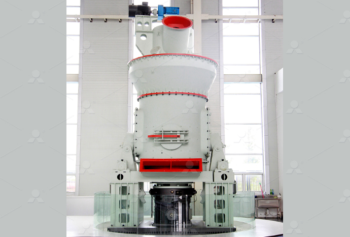
LM Vertical Roller Mill
Input size:38-65mm
Capacity: 13-70t/h

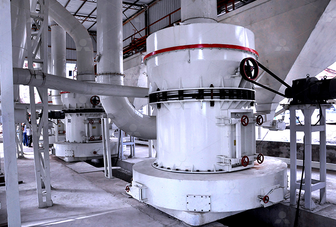
Raymond Mill
Input size:20-30mm
Capacity: 0.8-9.5t/h

Sand powder vertical mill
Input size:30-55mm
Capacity: 30-900t/h

LUM series superfine vertical roller grinding mill
Input size:10-20mm
Capacity: 5-18t/h

MW Micro Powder Mill
Input size:≤20mm
Capacity: 0.5-12t/h

LM Vertical Slag Mill
Input size:38-65mm
Capacity: 7-100t/h
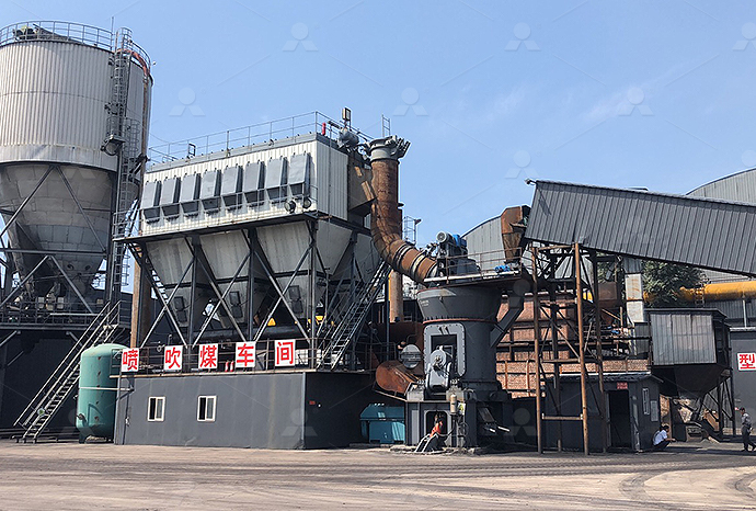
LM Vertical Coal Mill
Input size:≤50mm
Capacity: 5-100t/h
TGM Trapezium Mill
Input size:25-40mm
Capacity: 3-36t/h

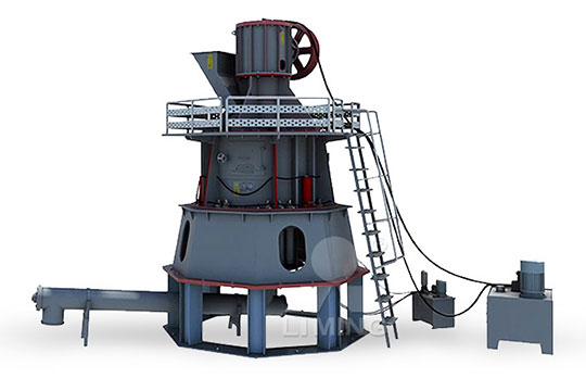
MB5X Pendulum Roller Grinding Mill
Input size:25-55mm
Capacity: 4-100t/h
Straight-Through Centrifugal Mill
Input size:30-40mm
Capacity: 15-45t/h
Hydraulic grinding production line control circuit diagram

Lecture 26 HYDRAULIC CIRCUIT DESIGN AND ANALYSIS
HYDRAULIC CIRCUIT DESIGN AND ANALYSIS Example 114 Design a car crushing system The crushing force required is such that a 15 cm diameter cylinder is required at a working Figure shows a circuit where speed control of a hydraulic motor ( Bi directional motor) is accomplished using a flow control valve to control the fluid flow to the motor In the spring LECTURE 24 TO 26 HYDRAULIC CIRCUIT DESIGN FREQUENTLY All hydraulic units and their connections must be shown on the circuit diagram The hydraulic schematic forms the basis of the pipework of the system and –– together with the function Circuit diagram HAWE HydraulikExplain various hydraulic circuits to control singleacting and doubleacting cylinders Explain a regenerative circuit and determine the loadcarrying capacities Describe the working of a Lecture 24 HYDRAULIC CIRCUIT DESIGN AND ANALYSIS
.jpg)
Hydraulic Circuit for Surface Grinding Machine
The hydraulic circuit of the surface grinding machine utilizes a power pack to supply pressurized oil, one pilotoperated direction control valve which decides the direction of the flow of pressurized oil, and a doubleacting cylinder with advanced trainees with practical knowledge in the fields of hydraulics, automation (electrical drive and control technology, mechatronics) and pneumatics The modular training systems Hydraulics Basic Principles Bosch Rexroth WE MOVE YOU WINAccurate diagrams of hydraulic circuits are essential to the man who must repair them The diagram shows how the components will interact It shows the field technician how it works, Section 35 Chapter 1Lecture 24 HYDRAULIC CIRCUIT DESIGN AND ANALYSIS Learning Objectives Upon completion of this chapter, the student should be able to: Identify the graphic symbols for various types of hydraulic components Explain various Lecture 24 HYDRAULIC CIRCUIT DESIGN AND
.jpg)
Advanced process control for grinding circuits ABB
Figure 1— Typical grinding circuit scheme An optimal grinding process controller must manage to maintain a given fresh feed level while keeping the product size within a given range To Once this vital concept is mastered, both hardwired relay control circuits and PLC programs become possible to understand Without mastering this vital concept, neither relay control circuits nor PLC programs may be understood Relay Circuits and Ladder Diagrams ControlHydraulics in battery cell production Hydraulic power units in explosive environments Differences in lithiumion cell All hydraulic units and their connections must be shown on the circuit diagram The hydraulic schematic forms the basis of the pipework of the system and –– together with the function diagram — forms the basis of the Circuit diagram HAWE HydraulikDump Truck 3 Line System 45 QDB Manual Spreader Valve with Power Beyond 46 PSM 1000 Spreader Valve No In Cab Hydraulics 47 PSM Spreader Valve With LS 48 Hydraulic System Components: Pilot Control Valves VP04 Pneumatic Controls PCL04 Hydraulic Controls 14 Hydraulic System Components: Electronic Controls 15Training Basic Hydraulics Parker Hannifin
Increasing Grinding Circuit Robustness with Advanced Process Control
More complex ore bodies with lowering grades increase the challenges of maintaining high throughput, energy efficiency and required particle size for optimal downstream processing in grinding circuits Continuous and often rapidly changing characteristics of the mill feed requires constant focus to operate the circuit at optimal level Modern process instruments, online Hydrauliccircuit diagrams are complete drawings of a hydraulic circuit It includes the description, a sequence of operations, notes, and a components list Such diagrams are essentially required by the designers, the machine makers and mechanics to repair itLesson 28 Hydraulic circuit diagrams and troubleshootingThe hydraulic circuit for a milling machine is comparatively different from the hydraulic circuit of the surface grinding machine and hydraulic circuit of the shaper machineThis is because the table movement in milling operation is comparatively slower Also, the different feeds or you can say adjustable feeds are required for milling different types of workHydraulic Circuit for Milling Machine Explained In Details2019年11月16日 The hydraulic press circuit diagram could be considered one of the most essential pieces of equipment used in modern engineering Comprised of a series of pumps, valves, and cylinders, the hydraulic press circuit diagram is utilized for a variety of tasks ranging from manufacturing to assembly line functionsHydraulic Press Circuit Diagram Wiring Digital and Schematic
.jpg)
Basic Diagrams and Systems Engineering Library
This page provides the chapter on basic fluid power diagrams and fluid power systems from the US Navy's fluid power training course, NAVEDTRA 14105A, "Fluid Power," Naval Education and Training Professional Development and Technology Center, July 2015 Other related chapters from the Navy's fluid power training course can be seen to the right2017年9月23日 The hydraulic circuit diagram is a key tool that allows engineers to effectively control a mill which can be operated by hydraulic actuators This diagram breaks down the construction and function of each part within the system, and shows the flow of fluid to the actuators Essentially, the hydraulic circuit controls the movement of the milling Hydraulic Circuit Diagram For Milling Machine2022年12月1日 Hydraulic control schematic diagram Working principle: First, open the main switch and connect the oil circuit The signal obtained by the twoposition, threeway reversing valve is placed in the Design of hydraulic pneumatic control system for rail grinding car2018年6月8日 Hydraulic circuits are used to control the pressure of the hydraulic fluid, allowing it to go where it is needed in order to complete certain tasks The hydraulic circuit diagram of an injection molding machine is a visual Hydraulic Circuit Diagram Of Injection Molding

Simplified excavator hydraulic circuit Download
Download scientific diagram Simplified excavator hydraulic circuit from publication: A MultiActuator DisplacementControlled System with Pump Switching A Study of the Architecture and Introduction to Hydraulic Circuit (System) Hydraulic System: The controlled movement of parts or a controlled application of force is a common requirement in the industries These operations are performed mainly by using electrical Hydraulic Circuit (System) – Parts, Application, A small hydraulic press for Vbending operation is designed, manufactured and modeled The hydraulic bending press consists of hydraulic circuit, punch, die and PLC control unit Automation studio and SimHydraulic in Matlab/Simulink library are used to model the hydraulic circuit Using PLC program, the bending operation is controlledDESIGN, MANUFACTURE AND SIMULATE A HYDRAULIC 2022年6月8日 1 Identifying the line types In a hydraulic schematic, each line type has a unique meaning In addition, colors can be added to indicate purpose of the line In the figure below, all of the basic line types are shown The basic line is a solid The Best Way to Read a Hydraulic Schematic Mentored Engineer

Hydraulics Systems Diagrams and Formulas Cross MFG
Hydraulics Systems Diagrams and Formulas for a front end loader, winch, logsplitter, A return line filter is used to prevent contamination Winch The diagram shows a winch powered by a hydraulic motor The directional control valve with builtin relief features optional flow control to control the speed of the winch 2021年3月23日 5 Hydraulic circuit for Shaper M/c Fig shows the hydraulic circuit for operation of shaper Here meter out circuit is used It consists of hydraulic power unit which delivers the oil at constant pressure A double acting cylinder is used to reciprocate the ram A pivot actuated DC valve is used to alter the direction of stroke of the piston When spool is in right envelop mode, 3 industrial hydraulic circuits shapping, milling, drillingHYDRAULIC CIRCUIT FOR A SURFACE GRINDING MACHINE 1 Functional and Operational Requirements • In a surface grinding machine (or a milling machine) the work piece is clamped on the machine table and the machine table is made to reciprocate continuously with same speed during both forward and return strokes The continuous reciprocation of machine table is Hydraulic circuit for a surface grinding machineControl circuit that has the task of adapting the rotation speed (eg of a hydraulic motor) as a controlled variable as accurately as possible to a setpoint This action can be undertaken by changing the flow Q 2, ie the pump delivery flow (Figure D 41) , Speed control circuit HAWE Hydraulik
Hydraulic Schematic Symbols : How To Read A Hydraulic
Directional Control Valves Manual: Shown as a valve symbol with an actuator lever; Solenoid: Indicated by a square with a diagonal line and a circle at one end, representing the solenoid actuator; Pilotoperated: Combines basic valve symbols with additional lines or symbols indicating pilot control; Pressure Control Valves Relief Valves: Typically depicted with an Evaluate the performance of hydraulic circuits using various hydraulic elements 11 Introduction A hydraulic circuit is a group of components such as pumps, actuators, control valves, conductors and fittings arranged to perform useful Lecture 24 HYDRAULIC CIRCUIT DESIGN AND hydraulic oil in motion and at rest in a system to transmit or generate force for hydraulic clamping applications Circuit is the routing and control of a confined liquid to apply power This power is used to achieve a specific function resulting in work being performed For the discussions in thisFUNDAMENTAL TECHNICAL HYDRAULIC CLAMPING INFORMATION 61 Comparison of Hydraulic Pneumatic Circuits Hydraulic Circuits Pneumatic Circuits 1 Working fluid used is oil 1 Working fluid used is air 2 The operation is complicated 2The operation is simple 3 The operation is quiet 3 The operation is noisy 4 To pressurized the oil, pump is necessary 4 Air compressor is necessary 5CHAPTER 6 HYDRO PNEUMATIC SYSTEMS CIRCUITS By Prof
.jpg)
Hydraulic Circuit Diagram With Explanation Wiring Draw And
2023年3月21日 What is a Hydraulic Circuit Diagram? A hydraulic circuit diagram is a visual representation of a hydraulic system in which components are identified by symbols and connected with lines to show their relationship These diagrams are used to illustrate how hydraulic systems, such as those found in cars and trucks, power machinery, and even some The above circuit shows the operation of the hydraulic circuit of the shaping machine when it is in idle condition A 4 x 3 direction control valve is used in this circuit 4×3 DCV means DCV has four ports and three stagesHydraulic Circuit for Shaping Machine Explained In Detailshydraulic fluids 296 4 Basic circuits of hydraulics 297 41 Circuit diagrams in hydraulics 297 411 Graphical illustration of hydraulic circuits 297 42 Open and closedloop control with valves 300 421 Openloop control with directional control valves 300 Hydraulics Basic Principles Bosch Rexroth WE MOVE YOU WINDownload scientific diagram 9: Hydraulic circuit diagram of the threepiston digital inline pumpmotor with a camshaft pushing the pistons (modified from Linjama, 2009b) The flow can be 9: Hydraulic circuit diagram of the threepiston digital inline

COMPACT HYDRAULIC SHEARING MACHINE Production
“caution”hydraulic oil specification 1 use hydraulic oil aw46 shell brand or equivalent specification of other brands 2 fill hydraulic oil into hydraulic tank up to 90% full (before running this machine, please do not forget to fill hydraulic oil aw46 shell brand 60 liters into oil tank) do not rely on oil gauge which sometimes give2024年6月28日 Introduction In the world of electronics and engineering, the ability to read and interpret schematics is a fundamental skill But what exactly are schematics, and why are they so important? Schematics, or circuit diagrams, are visual representations of electronic circuitsThey use symbols to represent different electronic components and show how these components The Basics of Schematics: Understanding Circuit Diagrams andTeam License The SmartDraw team License puts you in control with powerful administrative features Security See how we keep your data safe Apps Integrations SmartDraw has templates and symbols for all sorts of engineering diagrams including schematic drawings, wiring diagram, circuit diagrams, electrical plans, and much moreSchematic Diagram Maker Free Online App SmartDrawOnce this vital concept is mastered, both hardwired relay control circuits and PLC programs become possible to understand Without mastering this vital concept, neither relay control circuits nor PLC programs may be understood Relay Circuits and Ladder Diagrams Control
.jpg)
Circuit diagram HAWE Hydraulik
Hydraulics in battery cell production Hydraulic power units in explosive environments Differences in lithiumion cell All hydraulic units and their connections must be shown on the circuit diagram The hydraulic schematic forms the basis of the pipework of the system and –– together with the function diagram — forms the basis of the Dump Truck 3 Line System 45 QDB Manual Spreader Valve with Power Beyond 46 PSM 1000 Spreader Valve No In Cab Hydraulics 47 PSM Spreader Valve With LS 48 Hydraulic System Components: Pilot Control Valves VP04 Pneumatic Controls PCL04 Hydraulic Controls 14 Hydraulic System Components: Electronic Controls 15Training Basic Hydraulics Parker HannifinMore complex ore bodies with lowering grades increase the challenges of maintaining high throughput, energy efficiency and required particle size for optimal downstream processing in grinding circuits Continuous and often rapidly changing characteristics of the mill feed requires constant focus to operate the circuit at optimal level Modern process instruments, online Increasing Grinding Circuit Robustness with Advanced Process ControlHydrauliccircuit diagrams are complete drawings of a hydraulic circuit It includes the description, a sequence of operations, notes, and a components list Such diagrams are essentially required by the designers, the machine makers and mechanics to repair itLesson 28 Hydraulic circuit diagrams and troubleshooting

Hydraulic Circuit for Milling Machine Explained In Details
The hydraulic circuit for a milling machine is comparatively different from the hydraulic circuit of the surface grinding machine and hydraulic circuit of the shaper machineThis is because the table movement in milling operation is comparatively slower Also, the different feeds or you can say adjustable feeds are required for milling different types of work2019年11月16日 The hydraulic press circuit diagram could be considered one of the most essential pieces of equipment used in modern engineering Comprised of a series of pumps, valves, and cylinders, the hydraulic press circuit diagram is utilized for a variety of tasks ranging from manufacturing to assembly line functionsHydraulic Press Circuit Diagram Wiring Digital and SchematicThis page provides the chapter on basic fluid power diagrams and fluid power systems from the US Navy's fluid power training course, NAVEDTRA 14105A, "Fluid Power," Naval Education and Training Professional Development and Technology Center, July 2015 Other related chapters from the Navy's fluid power training course can be seen to the rightBasic Diagrams and Systems Engineering Library2017年9月23日 The hydraulic circuit diagram is a key tool that allows engineers to effectively control a mill which can be operated by hydraulic actuators This diagram breaks down the construction and function of each part within the system, and shows the flow of fluid to the actuators Essentially, the hydraulic circuit controls the movement of the milling Hydraulic Circuit Diagram For Milling Machine
Design of hydraulic pneumatic control system for rail grinding car
2022年12月1日 Hydraulic control schematic diagram Working principle: First, open the main switch and connect the oil circuit The signal obtained by the twoposition, threeway reversing valve is placed in the